
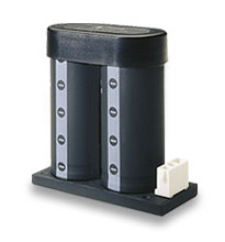
The ENMod system is an AC front-end solution combining passive Power Factor Correction and autoranging function. It consists of the MiniHAM passive harmonic attenuation module and the FARM3 autoranging AC-DC front-end module. Combined with filtering and hold-up capacitors, the ENMod system provides full compliance to EN61000-3-2 Harmonic Current, EN55022, Level B Conducted Emissions, EN61000-4-5 Surge Immunity, EN61000-4-11 Line Disturbances, and EN61000-3-3 Inrush Current.
Unlike active PFC solutions, the MiniHAM generates no EMI, greatly simplifying and reducing system noise filtering requirements. It is also smaller and more efficient than active alternatives. Optimized for operation on the DC bus (provided by the FARM3) rather than directly on the AC line, it will provide harmonic current compliance at up to 600 W of input power at 230 Vac.
The FARM3 is a filter and autoranging module that has been optimized for use as the front end for the MiniHAM. Both modules are in Vicor’s standard Mini half-brick package.
- 90 – 132 Vac
- 180 – 264 Vac
- 575 W
- 94 – 97% (typical)
- 2.28″ x 2.2″ x 0.5″ (57,9 x 55,9 x 12,7 mm)
- Autoranging 115/230 Vac input
- Harmonic current attenuation to EN61000-3-2
- EMI filtering to EN55022, Level B (with recommended filter)
- Transient immunity to EN61000-4-5
- Microprocessor control
- Inrush current limiting
Download Individual Chapters
- High Density DC-DC Converter Technology
- Control Pin Functions and Applications
- Design Requirements
- EMC Considerations
- Current Sharing in Power Arrays
- Thermal Performance Information
Accessory Modules
- Autoranging Rectifier Module (ARM)
- Filter / Autoranging Rectifier Module (FARM)
- Modular AC Front-end System (ENMod)
- High Boost HAM
- Filter Input Attenuator Module (FIAM)
- Output Ripple Attenuator Module (MicroRAM)
Recommended Soldering Methods
Mounting Options
| 2-D Mini-size Drawings | ||||
| Drwg. Number | Description | Download | RoHS | |
| 25006 | Outline drawing for Mini DC-DC Converter | DXF | PDF | ||
| 3-D Mini-size Module (referring to drawing number 25006) | ||||
| Mini, short tin / lead pin, slotted baseplate | STEP | 3D PDF | |||
| Mini, short tin / lead pin, threaded baseplate | STEP | 3D PDF | |||
| Mini, short tin / lead pin, through-hole baseplate | STEP | 3D PDF | |||
| Mini, long tin / lead pin, slotted baseplate | STEP | 3D PDF | |||
| Mini, long tin / lead pin, threaded baseplate | STEP | 3D PDF | |||
| Mini, long tin / lead pin, through-hole baseplate | STEP | 3D PDF | |||
| Mini, short ModuMate, slotted baseplate | STEP | 3D PDF | |||
| Mini, short ModuMate, threaded baseplate | STEP | 3D PDF | |||
| Mini, short ModuMate, through-hole baseplate | STEP | 3D PDF | |||
| Mini, long ModuMate, slotted baseplate | STEP | 3D PDF | |||
| Mini, long ModuMate, threaded baseplate | STEP | 3D PDF | |||
| Mini, long ModuMate, through-hole baseplate | STEP | 3D PDF | |||
| Mini, short gold pin (RoHS), slotted baseplate | STEP | 3D PDF | |||
| Mini, short gold pin (RoHS), threaded baseplate | STEP | 3D PDF | |||
| Mini, short gold pin (RoHS), through-hole baseplate | STEP | 3D PDF | |||
| Mini, long gold pin (RoHS), slotted baseplate | STEP | 3D PDF | |||
| Mini, long gold pin (RoHS), threaded baseplate | STEP | 3D PDF | |||
| Mini, long gold pin (RoHS), through-hole baseplate | STEP | 3D PDF | |||
These calculator programs allow users to determine values that help with accessory
component selection for power system design.
Hold-up Capacitor Calculator
Thermal Calculators
- Thermal impedance calculator
- Thermal data and heat sink selection tool
This is a downloadable Excel file.
| Description | P/N | Capacitance | Voltage Rating | RoHS | Technical Drawing | ||||||
| Capacitors | |||||||||||
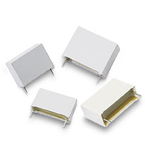 |
X-Cap | 03047 | 0.47 µF | 250 Vac | PDF | DXF | ||||||
| X-Cap | 02573 | 1 µF | 250 V | PDF | DXF | |||||||
| X-Cap | 00927 | 0.33 µF | 275 V | PDF | DXF | |||||||
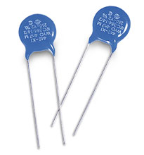 |
Y-Cap | 01000 | 4,700 pF | 250 Vac | PDF | DXF | ||||||
| Y-Cap Surface Mount | 25283 | 4,700 pF | 250 Vac | PDF | DXF | |||||||
| Multilayer Film Cap | 34610 | 0.61 µF | 250 V | PDF | DXF | |||||||
| MOVs | |||||||||||
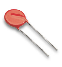 |
14 mm Disc | 30076 | 275 V | PDF | DXF | |||||||
| 10 mm Disc | 30234-220 | 275 V | PDF | DXF | ||||||||

| Description | P/N | Capacitance | Height of HUB |
RoHS | Technical Drawing | ||||||
 |
Holdup Box | HUB820-S | 410 µF | 1.55″ | PDF | DXF | ||||||
| Holdup Box | HUB1200-S | 600 µF | 1.75″ | PDF | DXF | |||||||
| Holdup Box | HUB1800-S | 900 µF | 2.14″ | PDF | DXF | |||||||
| Holdup Box | HUB2200-S | 1,100 µF | 2.85″ | PDF | DXF | |||||||
| Holdup Box | HUB2700-S | 1,350 µF | 3.52″ | PDF | DXF | |||||||
| Holdup Box | HUB3300-S | 1,650 µF | 3.52″ | PDF | DXF | |||||||
| HUB contains two (2) capacitors of the value shown. | |||||||||||
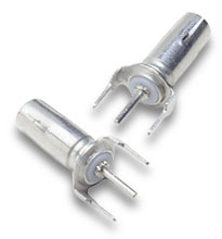
| Mounting Connector Kit | |||||||||||
| Used for P/N HUB820-S, HUB1200-S, and HUB1800-S | 21393 | PDF | DXF | |||||||||
| Used for P/N HUB2200-S, HUB2700-S, and HUB3300-S | 21394 | PDF | DXF | |||||||||
| Kit contains one connector and pins. | |||||||||||

 |
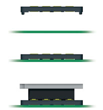
SurfMates – Surface-mount Sockets | All SurfMates are RoHS Compatible | |||||||||||
| Board Thickness | Mounting | Assembly Drawing | Converter Pin Style* | Module Style | Input P/N** |
Output P/N** | 5 In/Out Sets P/N | Technical Drawing | |||||
| All | surface | PDF | DXF | F | Mini | 22100 | 22102 | 16021 | PDF | DXF | |||||
| Example of SurfMate Application | |||||||||||||
| * F = Short Gold (RoHS), G = Long Gold (RoHS) ** For individual input / output purchases, a 35-piece minimum (and multiples) applies to Maxis / Minis and a 40-piece minimum (and multiples) for Micros. |
|||||||||||||
 |
InMates – Through-hole | All InMates are RoHS Compatible | |||||||||||
| All sockets are supplied on InMate headers to assure proper alignment during installation. | |||||||||||||
| Board Thickness (nominal) | Board Thickness (min / max) |
Mounting | Converter Pin Style* | Module Style | Input P/N** | Output P/N** | 5 In/Out Sets P/N | Technical Drawing | |||||
| 0.063″ | 0.055″ / 0.071″ | inboard | F | Mini | 18374 | 18384 | 18366 | PDF | DXF | |||||
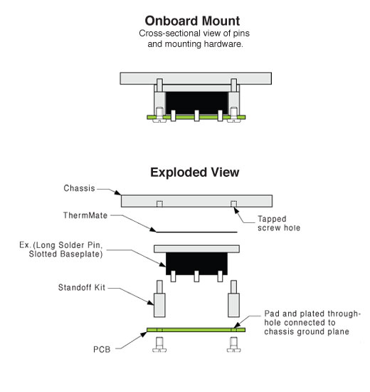
| 0.063″ | 0.055″ / 0.071″ | onboard | G | Mini | 18378 | 18390 | 18368 | PDF | DXF | |||||
| 0.094″ | 0.084″ / 0.104″ | inboard | F | Mini | 18375 | 18385 | 18367 | ||||||
| 0.094″ | 0.084″ / 0.104″ | onboard | G | Mini | 18379 | 18391 | 18369 | ||||||
| 0.125″ | 0.1125″ / 0.1375″ | onboard | G | Mini | 21539 | 21544 | 21511 | ||||||
| Example of Inboard Mounting Options Example of Onboard Mounting Options | |||||||||||||
| * F = Short Gold (RoHS), G = Long Gold (RoHS) ** For individual input / output purchases, a 35-piece minimum (and multiples) applies to Maxis / Minis and a 40-piece minimum (and multiples) for Micros. |
|||||||||||||
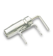
| Module Exchange Tools | |||||||||||||
| Description | Module Style | P/N | Technical Drawing | ||||||||||
 |
Used to facilitate the proper extraction of Mini modules from InMate or SurfMate sockets. | Mini | 22828 | – | |||||||||
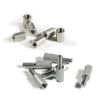 |
Standoff Kits for Solder Mounted Modules | All Standoffs are RoHS Compatible | ||||||||||||||
| Board Thickness | Mounting | Converter Pin Style | Baseplate | Heat Sink | Kit P/N* | Bag P/N** | Technical Drawing | |||||||||
| 0.063″ | inboard | F, Blank | slotted | thru-hole | 18150 | 19126 | PDF | DXF | |||||||||
| 0.063″ | inboard | F, Blank | slotted | threaded | 18151 | 19127 | PDF | DXF | |||||||||
| 0.063″ | inboard | F, Blank | thru-hole | thru-hole | 18146 | 19122 | PDF | DXF | |||||||||
| 0.063″ | inboard | F, Blank | thru-hole | threaded | 18147 | 19123 | PDF | DXF | |||||||||
| 0.063″ | inboard | F, Blank | threaded | thru-hole | 18146 | 19122 | PDF | DXF | |||||||||
| 0.063″ | onboard | G, L | slotted | thru-hole | 18156 | 19132 | PDF | DXF | |||||||||
| 0.063″ | onboard | G, L | slotted | threaded | 18157 | 19133 | PDF | DXF | |||||||||
| 0.063″ | onboard | G, L | thru-hole | thru-hole | 18150 | 19126 | PDF | DXF | |||||||||
| 0.063″ | onboard | G, L | thru-hole | threaded | 18152 | 19128 | PDF | DXF | |||||||||
| 0.063″ | onboard | G, L | threaded | thru-hole | 18150 | 19126 | PDF | DXF | |||||||||
| 0.093″ | inboard | G, L | slotted | thru-hole | 18150 | 19126 | PDF | DXF | |||||||||
| 0.093 “ | inboard | G, L | slotted | threaded | 18151 | 19127 | PDF | DXF | |||||||||
| 0.093 “ | inboard | G, L | thru-hole | thru-hole | 18146 | 19122 | PDF | DXF | |||||||||
| 0.093 “ | inboard | G, L | thru-hole | threaded | 18147 | 19123 | PDF | DXF | |||||||||
| 0.093 “ | inboard | G, L | threaded | thru-hole | 18146 | 19122 | PDF | DXF | |||||||||
| * Kits include six (6) standoffs and screws. Mini and Micro modules require a minimum of four standoffs. ** Bags of one hundred (100) do not include screws; #4-40 thread hardware required. |
||||||||||||||||
| Design Information for Solder Mounting | ||||||||||||||||
|
Standoff Kits for InMate Mounted Modules | All Standoffs are RoHS Compatible | ||||||||||||||
| Board Thickness | Mounting | Converter Pin Style | Baseplate | Heat Sink | Kit P/N* | Bag P/N** | Technical Drawing | |||||||||
| 0.063″ | inboard | S | slotted | thru-hole | 18153 | 19129 | PDF | DXF | |||||||||
| 0.063″ | inboard | S | slotted | threaded | 18154 | 19130 | PDF | DXF | |||||||||
| 0.063″ | inboard | S | thru-hole | thru-hole | 18148 | 19124 | PDF | DXF | |||||||||
| 0.063″ | inboard | S | thru-hole | threaded | 18149 | 19125 | PDF | DXF | |||||||||
| 0.063″ | inboard | S | threaded | thru-hole | 18148 | 19124 | PDF | DXF | |||||||||
| 0.063″ | onboard | N | slotted | thru-hole | 18158 | 19134 | PDF | DXF | |||||||||
| 0.063″ | onboard | N | slotted | threaded | 18159 | 19135 | PDF | DXF | |||||||||
| 0.063″ | onboard | N | thru-hole | thru-hole | 18153 | 19129 | PDF | DXF | |||||||||
| 0.063″ | onboard | N | thru-hole | threaded | 18155 | 19131 | PDF | DXF | |||||||||
| 0.063″ | onboard | N | threaded | thru-hole | 18153 | 19129 | PDF | DXF | |||||||||
| 0.093″ | inboard | S | slotted | thru-hole | 18153 | 19129 | PDF | DXF | |||||||||
| 0.093″ | inboard | S | slotted | threaded | 18154 | 19130 | PDF | DXF | |||||||||
| 0.093″ | inboard | S | thru-hole | thru-hole | 18148 | 19124 | PDF | DXF | |||||||||
| 0.093″ | inboard | S | thru-hole | threaded | 18149 | 19125 | PDF | DXF | |||||||||
| 0.093″ | inboard | S | threaded | thru-hole | 18148 | 19124 | PDF | DXF | |||||||||
| 0.093″ | onboard | N | slotted | thru-hole | 18156 | 19132 | PDF | DXF | |||||||||
| 0.093″ | onboard | N | slotted | threaded | 18157 | 19133 | PDF | DXF | |||||||||
| 0.093″ | onboard | N | thru-hole | thru-hole | 18150 | 19126 | PDF | DXF | |||||||||
| 0.093″ | onboard | N | thru-hole | threaded | 18152 | 19128 | PDF | DXF | |||||||||
| 0.093″ | onboard | N | threaded | thru-hole | 18150 | 19126 | PDF | DXF | |||||||||
| 0.125″ | onboard | N | slotted | thru-hole | 24054 | 19132 | PDF | DXF | |||||||||
| 0.125″ | onboard | N | slotted | threaded | 18157 | 19133 | PDF | DXF | |||||||||
| 0.125″ | onboard | N | thru-hole | thru-hole | 24056 | 19126 | PDF | DXF | |||||||||
| 0.125″ | onboard | N | thru-hole | threaded | 18152 | 19128 | PDF | DXF | |||||||||
| 0.125″ | onboard | N | threaded | thru-hole | 24056 | 19126 | PDF | DXF | |||||||||
| * Kits include six (6) standoffs and screws. Mini and Micro modules require a minimum of four standoffs. ** Bags of one hundred (100) do not include screws; #4-40 thread hardware required. |
||||||||||||||||
| Design Information for InMate Mounting | ||||||||||||||||
|
Standoff Kits for SurfMate Mounted Modules | All Standoffs are RoHS Compatible | ||||||||||||||
| Board Thickness | Mounting | Converter Pin Style | Baseplate | Heat Sink | Kit P/N* | Bag P/N** | Technical Drawing | |||||||||
| All | surface | S | slotted | thru-hole | 20178 | 20188 | PDF | DXF | |||||||||
| All | surface | F | slotted | threaded | 20179 | 20189 | PDF | DXF | |||||||||
| All | surface | F | thru-hole | thru-hole | 20176 | 20186 | PDF | DXF | |||||||||
| All | surface | F | thru-hole | threaded | 20177 | 20187 | PDF | DXF | |||||||||
| All | surface | F | threaded | thru-hole | 20176 | 20186 | PDF | DXF | |||||||||
| * Kits include six (6) standoffs and screws. Mini and Micro modules require a minimum of four standoffs. ** Bags of one hundred (100) do not include screws; #4-40 thread hardware required. |
||||||||||||||||
| Design Information for Surface Mounting | ||||||||||||||||
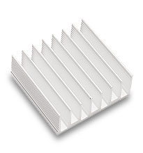
| Heat Sinks used with Vicor’s Mini-Size Modules (not for VI-J00 modules) | |||||||||||
| Description | P/N | RoHS | Technical Drawing | ||||||||
 |
0.40″ longitudinal fins, threaded mounting* | 32188 | PDF | DXF | ||||||||
| 0.90″ longitudinal fins, threaded mounting* | 30189 | PDF | DXF | |||||||||
|
|
|||||||||||
 |
0.40″ longitudinal fins, thru-hole mounting | 30195 | PDF | DXF | ||||||||
| 0.90″ longitudinal fins, thru-hole mounting | 30182 | PDF | DXF | |||||||||
|
|
|||||||||||
 |
0.40″ transverse fins, threaded mounting* | 30184 | PDF | DXF | ||||||||
| 0.90″ transverse fins, threaded mounting | 30269 | PDF | DXF | |||||||||
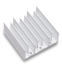 |
0.40″ transverse fins, thru-hole mounting | 30721 | PDF | DXF | ||||||||
| 0.90″ transverse fins, thru-hole mounting | 30724 | PDF | DXF | |||||||||
| * NOT for use with threaded baseplates | |||||||||||
| Heat Sink Thermal Data and Calculator | |||||||||||
| Low-Profile Side-Fin Heat Sinks (Height only 0.125″ above module baseplate) | |||||||||||
| Description | P/N | RoHS | Technical Drawing | ||||||||
|
|
|||||||||||
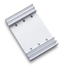 |
0.55″ Side-Fin Heat Sink for Mini-Sized Modules | 32190 | |||||||||
| Heat Sink Thermal Data and Calculator | |||||||||||
| ThermMate Thermal Pads (10 pieces per package) | |||||||||||
| Description | P/N | Thickness | RoHS | Technical Drawing | |||||||
 |
For use with Vicor Mini-size modules* | 20264 | 0.007″ | PDF | DXF | |||||||
| * NOT for use with VI-200 or VI-J00 modules | |||||||||||


