1.Premises
As the “energy saving” topic being mentioned frequently nowadays, power supply manufacturers keep chasing the high efficiency and low power consumption features. Power Factor (PF) is also another important element that affects energy usage, and the high PF products could save power plant from the environmental issue of generating more power, which is caused by lower PF power supplies, to operate devices. In this case, it is mandatory for most consumer products over 100 watts to label “Energy Star” which needs to meet at least PF value 0.9. In this article, we will discuss what is Power Factor Correction (PFC) for Cincon’s latest PFC module PFC 750.
2.PFC (Power Factor Correction) introduction
Starting from the explanation of the Power Factor (PF), the PF is a coefficient between -1 to 1 which is defined by the ratio of real power and apparent power (Refer to Fig. 1). In AC system, the harmonic currents would be generated during the process of implementing rectification techniques (AC to DC). To be more detailed, the harmonic currents are generated when the line voltage exceeds the cross voltage and then this causes the bulk capacitor to draw current and makes the current waveform discontinued. These harmonic currents distort the shape of current waveform and contribute to apparent power.
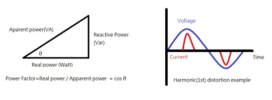 Fig. 1 Power Factor and Harmonic Current Distortion
The PFC is to correct distortion phenomenon and makes Voltage and Current waveform overlapped again to reduce reactive power. There are two methods to achieve the target of PFC function which are “Passive” and “Active”. The passive method utilizes inductor and capacitor to reduce the peak current effect. On the other hand, the active method utilizes boost converter to increase the switching frequency and control the shape of waveform of input current. Both methods have pros and cons. However, the active PFC method is more widely used because it is easier to reach the target of high PF value.
3.Features of PFC 750 module
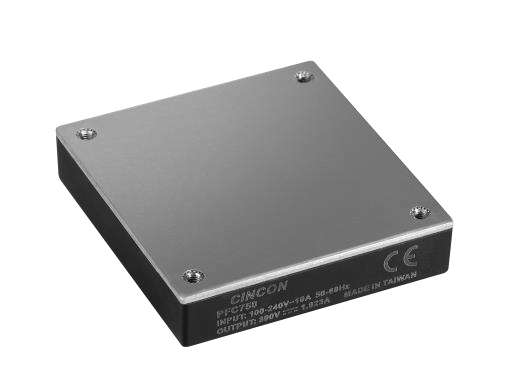
PFC750 is a standard half-brick and low-profile size AC-DC power converter. It has the universal input range 90-264Vac and 390Vdc output. Its power factor could be up to 0.99 and provides 750 Watts power. The PFC750 is designed by boost converter and its efficiency could reach up to 96.5% and the operating case temperature range is -40°C to 100°C. The module has longer lifetime due to not having electrolytic cap inside which increases the reliability of the product.
Functional pin description:
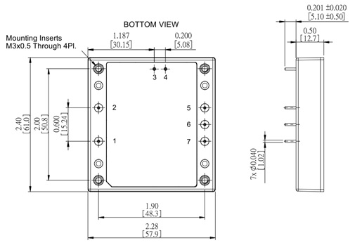
Fig.2 PFC 750 mechanical drawing

*Note 1: Enable pin is designed to connect to the remote on/off pin of DCDC converter as Power Good signal.
4.Application
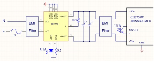
Fig.3 Application Circuitry
In the system application, the power loop concept is the combination of front-end AC-DC PFC module and back-end DC-DC converter. With additional external components, this power loop circuity could meet the system requirements such as hold-up time, inrush current limit and power good signal features. One big advantage of choosing PFC and DC-DC modular design is that designers have more flexibility to adjust volume of external components and not to be restricted by size limitation. The detail of reference design information could be found in application note.
The following is the prototype of evaluation board of PFC750 and CFB750-300S combination, which has been verified to meet EMI Class A standard. With the help of evaluation board, system engineers could quickly test the performance and adjust the volume of external component to meet system requirement. In addition, the other potential combinations of PFC750 and other high voltage input DCDC converter are possible such as two of CHB300-300S or four of CQB150-300S in parallel. This makes the configurable structure able to be implemented efficiently in the system.

Fig.4 Top of EVB_EMI filter & Electrolytic Cap
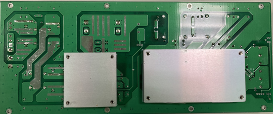
Fig.5 Bottom of PFC750 EVB_PFC750 & CFB750-300S
5.Testing results (Efficiency, Power Factor, Power derating curve, EMI testing result_Class A by EVB)
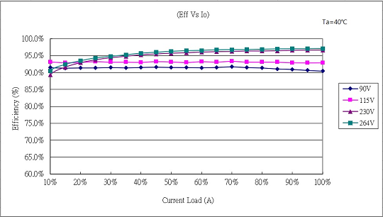
Fig.6 Efficiency @ 40℃
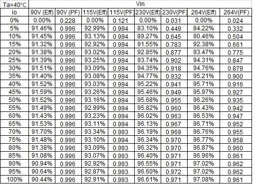
Fig.7 Table of Efficiency and Power Factor @ 40℃

Fig.8 Power derating curve with Heat-sink
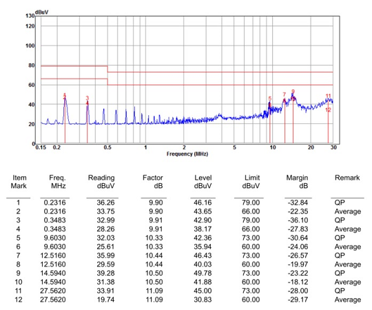
Fig.9 PFC 750 EMI Conduction report (Class A) by EVB
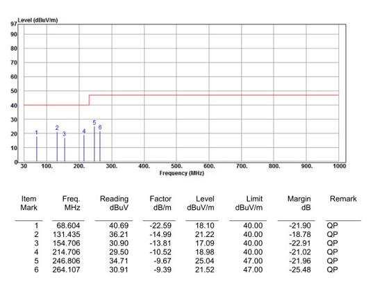
Fig.10 PFC 750 EMI Radiation report (Class A) by EVB
6.Conclusion
With the compact size and reliable brick power modules, system engineers have more flexibility to design their power loop circuitry for small space and harsh environment. Cincon keeps innovating the power supply technology and providing leading edge techniques to our customers. Moreover, Cincon has the strong and experienced R&D team to offer solutions to easing the burden of system application for customers.
Contact for more support: office@vitecpower.com

