 PMBus is an open-standard power management bus that extends the I2C bus protocol, specifically tailored for power management applications. Launched in 2005 by a group of power and semiconductor companies, PMBus was developed to address the challenges these companies faced in effectively communicating with their power systems. The collaboration resulted in a standard that enables system developers to configure power supplies for specific tasks while monitoring the status and overall health of power systems.
In the realm of bus protocols, SMBus (System Management Bus) is a subset of I2C, while CANbus (Controller Area Network bus), developed by Bosch in the 1980s, serves a different purpose. PMBus, I2C, SMBus, and CANbus are all communication protocols applicable to power management, but they differ in their specific uses.
Here is a comparison of them:
|
Feature |
I2C |
SMBus |
PMBus |
CANBus |
|
Communication protocol |
Serial | Serial | Serial | Serial |
|
Data rate |
100 to 400 kHz | 100 to 400 kHz | 100 to 400 kHz | 1 to 10 Mbps |
| Communication distance | Short distance | Short distance | Short distance | Long distance |
| Applications | General purpose | General purpose | Power management | Automotive |
Table1 comparison of I2C, SMBus, PMBus, and CANBus
I2C is a general-purpose serial protocol with low cost and reliability. SMBus, derived from I2C, includes additional features such as expanded address space and CRC checksum. PMBus is a standard specifically designed for power management applications and has high reliability. Moreover, CANbus is intended for long-distance, high-reliability communications, especially in automotive environments, unlike the others which are better suited for short-distance communications like those on a motherboard.
Architecture and Command Structure of PMBus
1. Basic Packet Structure:
PMBus commands are broken down into several components: start condition, address, command code, data, verification, and stop condition. This detailed structure supports complex interactions and control.

Fig. 1 PMBus protocol (https://pmbus.org/)
2. Address Space:
PMBus can address up to 100 different devices, offering significant scalability. It supports multiple power management devices on the same bus, with over 100 standard command codes available for various monitoring and control functions.

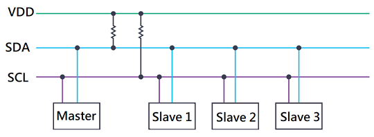
Fig. 2 prototype structure of PMSUS
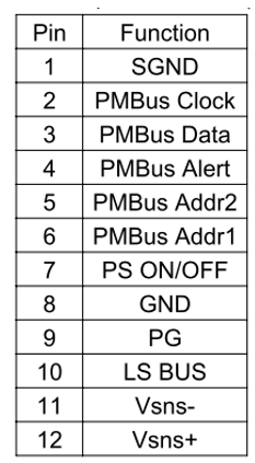
PMBus represents a powerful tool for contemporary power management needs. Its comprehensive framework, rich feature set, and adaptability make it an ideal solution for a multitude of fields and applications. By promoting smarter and more efficient power management, PMBus stands as a prominent standard that meets the ever-evolving demands of today’s technological landscape. It provides a comprehensive set of commands and instructions that can be used to manage various parameters of power supplies. To cater to future digital communication needs, CINCON just launched the CFM500S-PM (where PM stands for PMBus) with PMBus functionality. The related PMBus pin functions are as follows:

Table2 pin assignment of CN3 of CFM500S-PM
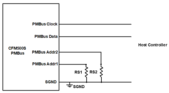
The PMBus application connection diagram is illustrated below. PMBus operates using bidirectional communication via the serial data line (SDA) and the serial clock line (SCL). As a result, each power supply needs only two signal lines to connect to the BUS terminal, fulfilling the requirements for control and monitoring, including reading power supply information. The CFM500S-PM can provide remote monitoring data, such as output voltage, output current, input voltage, and product temperature, as well as remote on/off control. These features are highly practical.
The PMBus application connection diagram is illustrated below. PMBus operates using bidirectional communication via the serial data line (SDA) and the serial clock line (SCL). As a result, each power supply needs only two signal lines to connect to the BUS terminal, fulfilling the requirements for control and monitoring, including reading power supply information. The CFM500S-PM can provide remote monitoring data, such as output voltage, output current, input voltage, and product temperature, as well as remote on/off control. These features are highly practical.

Fig. 3 PMBus application connection diagram of CFM500S-PM
Since the launch of the CFM500S series, it has received positive reviews from numerous customers. CINCON has also continuously made relevant optimizations to the product and added parallel connection features, further strengthening the competitive advantage of the CFM500S series. CINCON has now taken a step forward, adding PMBus function to this upgrade, supporting various communication needs between systems and power supplies. This expands the product’s application range to various industries like telecom equipment, IPC, industrial automation, test & measurement instrument, power management system, high-altitude and remote systems, and more other industrial applications. If you have any questions regarding this product upgrade, please refer to the latest datasheets and application note on the CINCON website or contact CINCON directly.
Datasheet: CFM500S
Contact us for support: office@vitecpower.com
