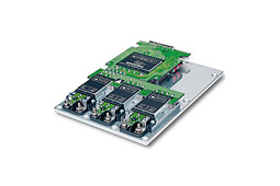
The VIPAC family of power systems is a unique class of user-defined, modular power solutions that is easily configured using Vicor’s PowerBench tools. It incorporates pre-assembled and tested front ends, Vicor Maxi, Mini and Micro series DC-DC converters , a choice of output connections and mechanical platforms. VIPAC can be specified with single, dual or triple outputs with voltages as low as 2 Vdc to as high as 48 Vdc and power levels from 50 – 900 Watts per output. VIPAC is available in a variety of packages with profiles as low as 0.75″. Product Change Notice
- 115/230 Vac autoranging, 47 – 440 Hz
- 2 – 48 Vdc
- 50 – 500 W/Output; Up to 900 W total
- See mechanical drawing on data sheet
- Single, dual or triple outputs
- Protective features: Inrush current limiting, transient protection, EMI filtering
- Choice of output terminations: LugMate or PlugMate
- Individual output control
- Rugged low profile coldplate
- Heat sink platforms available
- Component Power Solutions for Industrial High Voltage Applications
- Wide Range Trimming with Variable Loads
- High Efficiency Battery Charger Using Power Components
- AN: 201 – Using Modular DC-DC Converters to Meet European Standards for Railway Applications
- Adjustable Latching Output Over Current Circuit
- Hot Swap Capability Eliminates Down Time
- cURus – UL 60950-1,CSA 60950-1
- cTUVus – EN 60950-1, UL 60950-1, CSA 60950-1
- CE Marked – Low Voltage Directive (2006/95/EC) and RoHS Recast Directive(2011/65/EU)
- CB Certificate – IEC 60950-1
| AC Input Autoranging using both PlugMate and LugMate | |||||||||||
| Drawing Number |
Description | Maxi | Mini | Micro | RoHS | Technical Drawing | |||||
| 33015 | VIPAC Power System Configuration „A” | 3 | PDF |DXF | ||||||||
| 33016 | VIPAC Power System Configuration „B” | 2 | PDF |DXF | ||||||||
| 33017 | VIPAC Power System Configuration „C” | 2 | PDF |DXF | ||||||||
| 33018 | VIPAC Power System Configuration „D” | 2 | PDF |DXF | ||||||||
| 33019 | VIPAC Power System Configuration „E” | 1 | PDF |DXF | ||||||||
| 33020 | VIPAC Power System Configuration „F” | 1 | PDF |DXF | ||||||||
| 33021 | VIPAC Power System Configuration „G” | 1 | PDF |DXF | ||||||||
| DC Input using both PlugMate and LugMate | |||||||||||
| Drawing Number |
Description | Maxi | Mini | Micro | RoHS | Technical Drawing | |||||
| 21317 | VIPAC Power System Configuration „A” | 3 | PDF |DXF | ||||||||
| 21318 | VIPAC Power System Configuration „B” | 2 | PDF |DXF | ||||||||
| 21319 | VIPAC Power System Configuration „C” | 2 | PDF |DXF | ||||||||
| 21320 | VIPAC Power System Configuration „D” | 2 | PDF |DXF | ||||||||
| 21321 | VIPAC Power System Configuration „E” | 1 | PDF |DXF | ||||||||
| 21322 | VIPAC Power System Configuration „F” | 1 | PDF |DXF | ||||||||
| 21231 | VIPAC Power System Configuration „G” | 1 | PDF |DXF | ||||||||
These calculator programs allow users to determine values that help with accessory
component selection for power system design.
Trim Resistor Calculators
- Trim resistors for fixed output voltage trimming
- Trim resistors for variable output voltage trimming
Thermal Calculators
- Thermal data and heat sink selection tool
This is a downloadable Excel file.
- MicroRAM – Output Ripple Attenuator Module – The MicoRAM conbines both active and passive filtering to achieve greater than 40 dB of noise attenuation from over a range of 3 to 30 Vdc.
- QPO Family Output Filters – QPO filters use active filtering to reduce power supply ripple and noise in a 1.0″ x 1.0″ (25 x 25 mm) surface mount package.
| 115/230 Autoranging Input (Using HUB 820-s, 1200-s or 1800-s) | ||||||||
| Description | P/N | RoHS | Technical Drawing |
|||||
 |
HUB Connection | 21393 | ||||||
| AC Input Connector | 22499 | |||||||
| Input/Output Interface Connector | 22988 | |||||||
| Connector Kit | 23485R* | |||||||
| * Connector Kit includes HUB, AC Input & I/O Connectors | ||||||||
| 115/230 Autoranging Input (Using HUB 2200-s, 2700-s or 3300-s) | ||||||||
|
Description
|
P/N | RoHS | Technical Drawing |
|||||
 |
HUB Connector | 21394 | ||||||
| AC Input Connector | 22499 | |||||||
| Input/Output Interface Connector | 22988 | |||||||
| Connector Kit | 23485R* | |||||||
| * Connector Kit includes HUB, AC Input & I/O Connectors | ||||||||
| Description | Height of HUB |
Capacitance | P/N | RoHS | Technical Drawing | |||||||
 |
Holdup Box | 1.55″ | 410 µF | HUB820-S | ||||||||
| Holdup Box | 1.75″ | 600 µF | HUB1200-S | |||||||||
| Holdup Box | 2.14″ | 900 µF | HUB1800-S | |||||||||
| Holdup Box | 2.85″ | 1,100 µF | HUB2200-S | |||||||||
| Holdup Box | 3.52″ | 1,350 µF | HUB2700-S | |||||||||
| Holdup Box | 3.52″ | 1,650 µF | HUB3300-S | |||||||||
| HUB contains two (2) capacitors of the value shown. | ||||||||||||


